
Since the day that I was able to take apart my first toy, I have always wanted to fabricate my own PCB.
That long time dream finally came true when I decided I would tackle the challenge for the Robot Eraser project. Read that article first if you want to understand the project a bit better.
The objective of this PCB was to combine two power sources in order to power the Atmega chip. One power source is a DC solar panel and the other is an AC shake linear generator. Together they will power a robot which erases a dry erase whiteboard. Additionally the circuit features a programming bus on the left most section where I am able to connect an FTDI programmer.
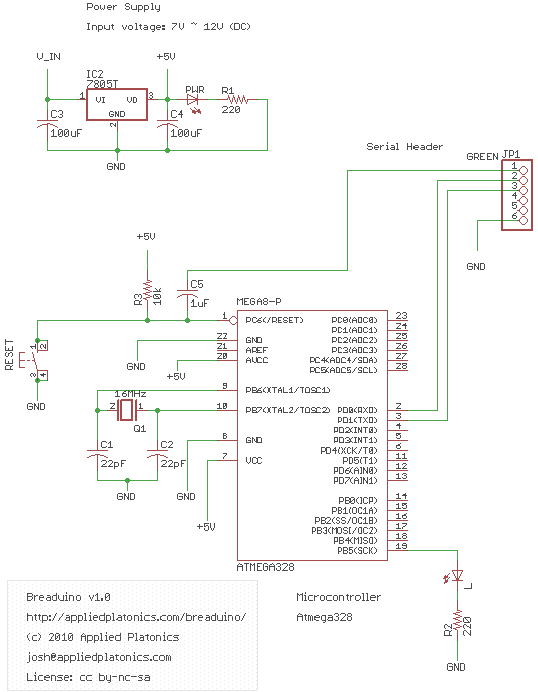 You may recognize that this schematic is very similar to a lillypad Arduino. That is because it is based on lillypad. The only difference between my PCB and a lillypad is the power circuit which combine the two sources of energy and the transistors to power two DC motors.
So how did I build it? Never having done PCB design I was able to quickly design and fabricate this board on my own. The first step was researching. I discovered a brilliant design called Ardweeny which inspired this board.
Ardweeny was designed to be the smallest possible Arduino with a through hole chip. The schematic is identical to a lillypad and is programmed in the same manner. Because the Robot Erasor was weight sensitive I decided to take this minimal approach with my own board. The source Altium files are provided by SolarRobotics for free. This meant that I was able to examine their schematic and design as I learned to make a PCB.
Before making a PCB one must decide which software to use. Eagle is very popular at my university and is very good for being free. Right off the bat I started with Eagle and became frustrated with Gerber export. Ultimately I decided to try Altium.
I downloaded a one month trial of Altium and it is a wonderful program. Because most professional designers prefer Altium, most open source PCB designs are in Altium file formats. Just download and then you can start to modify. I used this series of tutorials to learn Altium.
 |
| Both monitors of Altium. Schematic on Left. Complete board on right |
Some observations are that I did not make the holes on the four corners large enough to be useful. Also, LED2 is too close to Rst and both cannot fit.
After exporting the Gerber files I uploaded them to OSHpark where I was able to print three copies for $10! Free shipping and two week turnaround.

And that was it. The process is very simple once you get past the learning curve of the software. I look forward to designing many more boards soon to come.
